1.Intermac - .OTD file generation in
PLUS 2D Nesting Software
|
Setting of Path |
|
Creation of NC code for Intermac Machine using PLUS 2D is very simple. To get
that code file follow the procedure after optimization as given below.
Before you start generating the NC codes, you will need to do the following
one time setting.
1. Click on NC Links -> NC options menu. You will get a dialog box for
"NC Controller Settings..." as
follows.
|
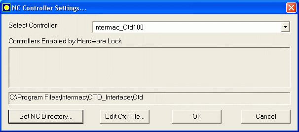
Figure 1 : Selecting controller and setting of
path. |
|
In that dialog box select Intermac_Otd100 as a controller
2. Specify the
path where you want to save the ".OTD" files.
Click on "Set NC Directory...", a Browse for Folder dialog, as shown below, will open, here you can select the folder in
which you want PLUS 2D to create the ".OTD" file.
For e.g.: Set the NC directory to
"C:\Program Files\Intermac\OTD_Interface\Otd".
|
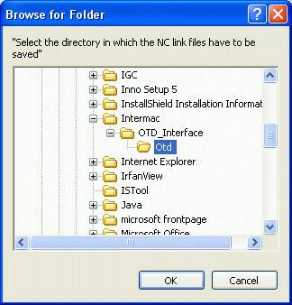
Figure 1 : Path selection for .OTD file
|
|
Generation of .OTD file in PLUS 2D
Once the above settings are done, you are ready to create
the NC code files.
1. Optimize the job and check out all the layouts.
2. Now, For generating the necessary code click on "Intermac_OTD100
CNC" button  from output
page. An ".OTD" file will be generated in the path specified in the NC options.
from output
page. An ".OTD" file will be generated in the path specified in the NC options.
|
Import .OTD file and Generating .CNI file
To make the CNI file from the OTD file we have to follow some simple steps as
given below.
1. Importing .OTD file...
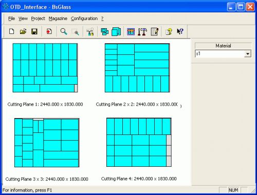
Click on File menu and select "Import OTD" or Press "Ctrl+I". A
file browse dialog appears. Then select the desired OTD file and click OK. Now
the layouts will be displayed in the Graphic Area, provided the Imported OTD
file is correct, along with the quantities and the sheet dimensions.
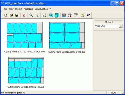
| Figure 1. Graphic area of OTD_Interface displaying layouts
from Imported OTD files |
 |
 |
|
Rectangular Shapes
|
Non - Rectangular Shapes
|
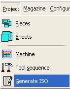
2. Generating the ISO program (.CNI for Genius CT)
| Now Goto "Project Menu" and
click "Generate ISO" option. A dialog for Selecting
Machine appears. |
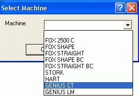
Selecting the Intermac Cutting Table
Click on the dropdown list and select
"Genius CT" and click OK. (Here you can select the machine which
available with you.)
|
|
|
 |
| Figure 2 : Selection of
"Generate ISO" menu |
Figure 3 : Selection of Machine |
Selecting the Cutting Wheels
After selecting the machine, cutting wheels has to be selected,
in the "Tool Sequence" dialog that appears next.
|
The upper part displays the tool sequences of all the materials contained in the imported “OTD” file, which are empty initially. Then select the desired sequence by clicking on the line, click to select the Type of tool and finally double-click on the tool Code. The tool will be added to the selected sequence, which must be made up of different types of tools and completed with all the types of tools present for the type of machine selected. Complete all the sequences, then press “OK” to confirm.
To delete a sequence and insert it again: select it with a mouse click and press the “Delete” (Del) key on the keyboard.
Saving the .CNI file for Genius CT
Now a file browse dialog appears, asking for the File Name for .CNI
file to be saved. Give the file name and the path "C:\WNC\User\iso"
to save the file and click
Save. This creates the required ".CNI" file that can be imported in
the Intermac "CNI WRT System" for cutting.
|
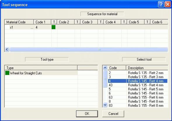
Figure 4 : Setting of tool sequence
|
|